Instructions
for
SCANNING TUNNELING MICROSCOPE
(STM)
By,
Eric Wittinger
Disassembling the STM
-
Open acoustic box
-
Disconnect the 2 main connectors (plug and coax cable) on STM (Figure
1)

Figure 1. Connectors.
-
Take STM unit our of acoustic box (Figure 2)
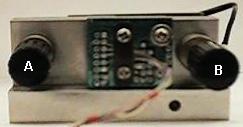

Figure 2. STM unit and Acoustic box.
-
Loosen course positioning screws (2) until sample holder is free. (figure
3)
-
Knob A twists counter clockwise to loosen
-
Knob B twists clock wise to loosen
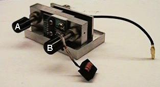
Figure 3. Positioning Knobs.
-
Remove sample holder from STM Module (Figure 4)
-
Careful not to damage the tip
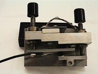
Figure 4. Sample holder.
Cleaning Sample
1. Supplies needed Scotch Tape.
-
Take a strip of tape and firmly press onto the sample on the sample
holder
-
Carefully remove the tape
-
While removing the tape you want a continuos layer of the sample material
to come off onto the tape.
-
Sometimes this does not occur and jagged flecks of the sample material
are left on the sample surface. These need to be removed with the tape
-
This is done by touching the tape to the sample until those areas are
smooth and one even lay of the sample is exposed
Changing the Tip
-
Remove the Sample plate
-
Remove the tip from the tip holder (Figure 5)
-
Use large magnifying glass with back lighting
-
Use needle fine tipped pliers to grip the tip
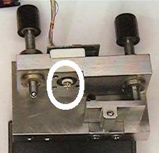
Figure 5. Tungsten Tip.
-
Select a new tip
-
Using fine tipped pliers pace ¼ of the tip into the tip holder
-
Slightly bend the tip to one side of the holder
-
Press the another ¼ of the tip into the holder
-
Slightly bend the tip in the opposite direction of step 5
-
Press the tip the rest of the way into the holder.
-
Note: This is done to hold the tip firmly in place.
Reassembling the STM and Adjusting the Tip
-
Carefully place sample holder plate into STM module (Figure 6)
Figure 6. Assembled STM Unit.
-
Using the 2 course adjusting screws roughly adjust the sample holder
to obtain a flat sample plain (See Figure 3)
-
Turn Knob A clockwise to tighten
-
Turn Knob B counterclockwise to tighten
-
Use a light microscope to due fine adjusting of the tip close to the
sample surface
(Figure 7)
-
CAUTION: Do not touch the tip to the sample. This will ruin the tip
-
Use the mirror image scene on the sample and the real image of the tip
as a guide to how close the tip is to the surface
-
Careful not to touch the surface with the tip. This will ruin the tip
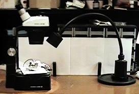
Figure 7. Light Microscope.
-
Place the STM module back into the acoustic box on the dampening unit
(Figure 8)
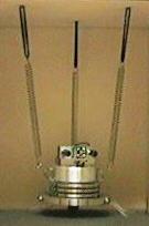
Figure 8. Dampening Unit.
-
Reattach the 2 main connectors (plug and coax cable)
Powering up the up STM
-
Turn on computer
-
Make sure the Isolation Power supply is hooked up to power the STM (Figure
9)
-
NOTE: If the Isolation power supply is not hooked up the image received
by the computer will be contaminated with noise for the standard power
socket
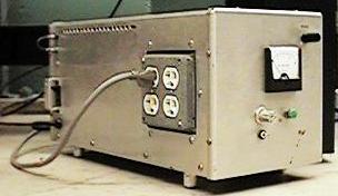
Figure 9. Isolation Power Supply.
-
Turn on the CSTM 9000 Unit I, power switch located on back of unit (Figure
10)
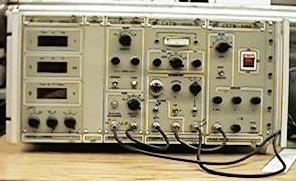
Figure 10. CSTM 9000 Unit.
-
Vbias = approximately 35 mv (Figure 11)
-
Iref = approximately
-0.99 nA (Figure 11)
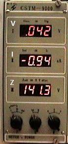
Figure 11. Vbias, Iref,
Zvoltage.
-
Turn on High Voltage Unit IV, a large
red toggle switch (Figure 12)
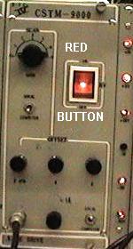
Figure 12. High Voltage Toggle.
Setting up Computer Program
-
NOTE: CNTL C will terminate the program
at any time
-
Locate VSCAN1.EXE on the computer
-
Change directories to C:\STM to Find VSCAN1
-
Run this program by typing VSCAN1 at prompt.
C:\STM\VSCAN1
-
Press <ENTER>
-
Main Menu will appear with options (Figure
13)
-
Title Acquisition Program
-
Quite to Menu -- Exits to main
menu
-
Option Topo -- Topographical scan
-
Sts scan -- Do not use this function,
(not operational)
-
Iv curve -- Do not use this function,
(not operational)
-
Move Tip -- Moves the tip
-
Change Para -- Do not use this
function, (not operational)
-
File Para -- Do not use this function,
(not operational)
-
Engrave -- Will make a trench in
the sample with the tip
Fine Adjustments of the STM
-
Use the 2 course adjustment screws to
move the tip close to the sample
-
CAUTION: This is a very sensitive procedure
-
Watch the Zvoltage as this
is done
-
Turn Knob B counter clockwise very slowly
to make the necessary adjustments
-
As Zvoltage approaches zero
volts stop the adjustment
-
The working range for the Zvoltage
= 15 0 volts
-
Reseal the acoustic box
-
Let system settle out vibrations for approximately
5 minutes.
To View Sample
-
Select T this will start the computer
scanning the sample
-
The computer screen will automatically
change and start to display the sample scans
-
ESC to return to the main menu
Other Modes of Scanning the sample
-
To change the scanning method flip the
output switch on the CSTM-9000 unit (Figure 13)
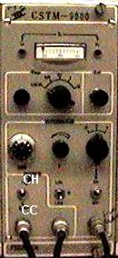
Figure 13. Scanning Method Switch.
-
CC Constant Current Scan
-
CH Constant Height Scan
Powering Down the STM
-
Quite VSCAN1 program
-
Open up Acoustic box and back the tip
away from the sample surface
-
Use Knob B and turn it clockwise
-
Adjust the tip until Zvoltage
= > +140
-
Turn off the High Voltage switch on the
CSTM-9000
-
Turn off unit I (Power switch is on back
of unit)